Important PRS considerations when operating close to an asset that is not rigidly fixed to the seabed
- DP Event
- Published on 18 September 2023
- Generated on 4 July 2025
- DPE 03/23
- 13 minute read
Observation
In recent years there have been a number of collisions between DP vessels near to a mobile asset, such as a drilling or heavy lift vessel.
Overview
It has come to the attention of the IMCA DP Committee that, in recent years, there have been a number of collisions between vessels undertaking DP operations near to a mobile asset, such as a drilling vessel, FPSO, or heavy lift vessel. The causes of these collisions could also impact offshore floating wind assets in the future.
From the DP Station Keeping Event reports received by IMCA, it is clear that the set-up and mixing of position reference systems have contributed to these events. The IMCA DP Committee wants to promote understanding to reduce incidents of this nature. Therefore, instead of identifying a Position Reference System as either absolute or relative, this bulletin defines absolute and relative DP positioning and provides examples of how the different position reference systems can be used in both circumstances.
IMCA DP Station Keeping Event reports, in recent years, confirm that the following issues were contributory factors:
- Setup and mixing of relative & absolute Position Reference Sensors (PRS).
- Lack of special functionality within the DP Control Systems to cope with the demands of relative position keeping of moving targets.
- Lack of focused training on the perils of mixing absolute and relative PRS without special DP functionality installed or in use.
- Lack of training in use of such special functionality.
- Improper PRS management along with operator error.
Absolute Position referencing
Absolute position referencing for station keeping is when the vessel maintains its position over a fixed point on the ground.
DGNSS has become by far the most used system for absolute referencing. Tautwire is a sub-surface system using its clump weight as the fixed reference point on the seabed. Similarly, hydro-acoustic, when the transponder is fixed to the seabed or fixed sub-surface structure, provides absolute position referencing.
Microwave and laser systems traditionally known as relative position references may also provide absolute positioning, providing their reference points are on fixed structures.
Relative Position referencing
Relative position referencing for station keeping is when the vessel maintains its position relative to an asset that may or may not be moving.
Typically, microwave and laser systems are used when a vessel is required to maintain position relative to another vessel or a structure that is not fixed to the seabed. This may include drilling vessels, FPSOs, heavy lift vessels and offshore floating wind assets. Relative DGNSS and accommodation support vessel gangways (with 3-axis measuring sensors) are also used for relative positioning. Hydro-acoustic systems can be used for relative positioning to track subsea vehicles such as ROV’s and trenchers in follow-sub mode or using the appropriate functionality of the DP control system.
Example:
As an absolute reference, a microwave system measures the bearing and distance from a transponder on a fixed asset. The vessel position is maintained over the ground, which is useful for tasks such as positioning a vessel alongside a fixed asset. As a relative position reference, the same system measures the bearing and distance from a transponder on a moving asset such as another vessel or other floating structure.
The hydro-acoustic reference system is used as an absolute reference when referencing a transponder on the seabed. Alternatively, the same system can be used for relative positioning when the transponder is located on a moving asset such as an ROV or trencher.
Weighting
Weighting is the process of assigning different levels of importance to different position reference systems (PRS). This is carried out to ensure that the DP system is using the most accurate and reliable data to control the vessel’s position.
There are a number of factors that can be considered when weighting PRS, including:
- The accuracy of the PRS
- The update rate of the PRS
- The stability of the PRS
- The availability of the PRS
In general, a PRS with higher accuracy, faster update rates, and greater stability will be given more weight than a PRS with lower accuracy, slower update rates, and less stability.
The weighting of PRS is typically assigned automatically by the DP control system’s software. The software will calculate a variance for each PRS, and the PRS with the lowest variance will be given the most weight. The variance is a measure of how much noise is present in the PRS data. Some older DP systems permit manual weighting adjustment.
PRS weighting is complex, but it is an important function in dynamic positioning. By understanding how weightings are assigned, DP operators can help to ensure that their vessels are operating safely and efficiently.
IMCA recommends that reference is made to specific OEM operational documentation for further details.
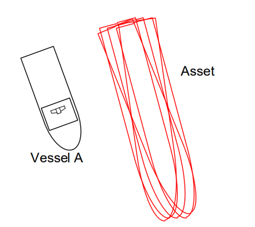
What are the concerns when operating next to a non-fixed structure?
The concerns become apparent when a combination of absolute and relative Position Reference Systems (PRS) are used. There is no conflict in the position measurements when a vessel is holding position adjacent to a fixed asset as all PRS are capable of absolute positioning and the DP system maintains the vessels position over the ground. However, when a vessel attempts to maintain position near to a moving asset, there is cause for concern as measurements between absolute and relative position reference systems will differ when the asset moves.
The DP control system estimates position based on motion in the “XY” plane of a measured reference. If the DP control system measures a PRS as moving and it is in use by the system (has weight) the system will compensate for the motion according to its auto-control model (position, heading, track, target, etc.). When the DP control system observes motion on a relative target which is considered “fixed” and it has a reference measuring the position of the vessel relative to earth “absolute” it will perceive the relative target motion as vessel drift. When both an absolute and relative target (in fixed mode) are compared, one is measuring motion of the controlled vessel and the other is measuring the position of the controlled vessel relative to the mobile asset. This can cause the DP control system to drive off station when it is compensating for motion of the reference asset rather than the vessel it has control over. The mitigating methods for these phenomena are explained in the following sections.
Mitigation
Mitigations to be considered:
Minimum Position Reference Systems online for Vessel A
Before executing DP Operations from a non-fixed asset, the operator (DPO) must examine the DP Control system and its capacity to accomplish the task safely. The operator must be aware of the capabilities of the DP Control system in order to choose which alternatives are most appropriate for the operation.
Option 2 below is not a recommended practice but it is known that the industry is utilising this method of vessel positioning. If Option 2 is to be used then the operator needs to know the risks of such an operation, the OEMs should always be consulted.
MSC.1/Circ.1580 3.4.8 Position reference systems – states:
.3 For equipment classes 2 and 3, at least three independent position reference systems should be installed and simultaneously available to the DP control system during operation.
.4 When two or more position reference systems are required, they should not all be of the same type, but based on different principles and suitable for the operating conditions.
Option one – Using Follow Target / Ship Follow Functionality:
- One absolute PRS (typically DGNSS)
- Two relative PRS with two targets (reflectors / responders on the asset) based on different principles, set as mobile targets and the DP control mode selected to Follow Target (Follow Position or Follow Position & Heading).
Note: Using Absolute PRS in conjunction with Relative PRS should only be considered if Vessel A is equipped with the appropriate follow target / ship follow functionality suitable for the Industrial Mission. I.e., capable of dealing with the expected movement velocities of the asset they are working with.
Note: Standard follow target functionality may not meet the performance criteria for the industrial mission. The OEM should be consulted.
Note: Redundancy of both absolute and relative reference systems should be considered.
Note: Vessels intending to follow position and heading of a target vessel will need multiple targets with horizontal spatial separation. OEM minimum recommended spatial separations is essential.
Note: The use of this functionality may necessitate the need for the operator to set up a ‘Reaction Radius/area’ when set to mobile follow target mode (position and heading) and select specific features (e.g. quick response, auto position fallback).
- Operator defined area within which the target can move without causing the vessel to follow.
- When the target is at the edge of reaction radius/area, the position setpoint is updated automatically to restore the vessel position relative to the target.
- Reaction radius/area is redrawn around the new position of the vessel.
Option two – Using Auto-position:
- One absolute PRS – set to monitoring
- Three relative PRS based on different principles such as Laser and Microwave – selected into DP Control without follow target mode (i.e. auto position mode).
Note: Practical experience has shown that employing relative targets with moving assets and not using follow target functionality allows the DP system to maintain a relative distance satisfactorily. This method avoids the additional risks involved in mixing absolute and relative PRS’s when maintaining a relative position off a moving asset, for DP Vessels without a bespoke Follow Target Functionality required for the Industrial Mission.
- The above approach can only work when the movement in surge sway and yaw of the target vessel is not excessive in velocity or distance.
- DP Operators must be diligent and competent to recognise degraded station keeping and take action to suspend ongoing operations and exit to safe zone. (E.g., excessive alarms and or movement of relative PRS’s, thruster oscillation, thrusters ramping up too quickly, etc.)
- OEMs are consistent that the Autopos mode with Kalman filter is not designed for this, even when only using relative systems. PRS’s may be rejected if the movement velocity of the target asset is excessive.
Lack of understanding of the functionality, improper/ineffective use of relative PRS and rapid / excessive movements of the target vessel may introduce unacceptable risk and consequences of a loss of position and or heading.
ASOG
The vessels Activity Specific Operating Guidelines (ASOG) needs to address the correct setup and calibration protocols. When an issue emerges, the operator must be provided with clear instructions to assist them in the execution of clear and concise action.
The development of the ASOG needs to explicitly consider and address the following:
- Verification of target locations (Targets on DP Control System display matching physical locations on target vessel)
- Proper target management (e.g. reinstatement in safe area, prediction errors at the DPCS or PRS receiver, instability in reference systems observed on DPCS, eroded confidence in reference system management by DPCS) Instruction on absolute PRS to be in monitoring mode and controls to ensure that Absolute PRS is not enabled if only relative PRSs are used for Station Keeping when in close proximity to target vessel (Close proximity to be defined (based on Industrial Mission)).
- Proper target management (e.g. reinstatement in safe area, prediction errors at the DPCS or PRS receiver, instability in reference systems observed on DPCS, eroded confidence in reference system management by DPCS) Instruction on absolute PRS to be in monitoring mode and controls to ensure that Absolute PRS is not enabled if only relative PRSs are used for Station Keeping when in close proximity to target vessel (Close proximity to be defined (based on Industrial Mission)).
- If “Follow-Target” Mode functionality is installed:
- Instructions specific to the version of the functionality installed and its use in the Industrial Mission being undertaken, including any specific features (e.g. auto position fallback functionality) – Applies to Option one only.
- Instructions specific to the version of the functionality installed and its use in the Industrial Mission being undertaken, including any specific features (e.g. auto position fallback functionality) – Applies to Option one only.
- Actions to be taken upon loss of redundancy:
Specific Operator interventions are required (note that variability exists in different versions of DP Control systems). ASOG must contain instructions relevant to the control system version that is installed.
For any option, it is imperative that OEM documentation is referred to and if necessary, OEMs are consulted regarding the best solution for the mission.
PRS Calibration – disabling and re-enabling the PRS
Calibration is used by the DP Control system to centre a PRS with the vessel model. This action should stay a stationary ‘correction’ after completion. If a PRS is then ‘re-calibrated,’ this might introduce unanticipated flaws in the model location, resulting in unexpected station-keeping difficulties.
Note: Frequent recalibration when in close proximity to an asset is not to be undertaken. If a need arises for recalibration when in close proximity, ongoing activities should be suspended and the vessel moved out to a safe position, recalibration carried out, stability of reference systems to be verified and steps used for initial set-up to be repeated to position vessel to resume Industrial mission.
It is important that calibration of each unit is current to ensure all offsets and bearings are correct in order to confirm the fore and aft lines as per OEM instructions. Prior to beginning operations, PRSs used must be confirmed and recorded to match the physical position on the host asset).
The operator needs to understand what is happening when the PRS diverges and how to respond. The typical DP Operator reaction is to reset the PRS (disabling and re-enabling the PRS) to bring it back to the central point. Such actions have the potential to induce position inaccuracies in the DP Model and vessel excursions with unacceptable outcomes when in close proximity to assets.
Note: All actions taken for the management of PRSs within the DP control system should align with the validated OEM design functionality of PRS management. (E.g., some DPCS are designed with a built-in function for aligning the error of PRS and others are not.)
Changes to PRS/DPCS (PRS related) set-up should not be attempted when in close proximity to assets.
DP vessel to another DP vessel interaction
When two DP vessels are engaged in interacting with each other and/or close quarter DP operations, one of the two DP vessels shall be designated as the ‘stationary’ or ‘master’ vessel. When possible, this vessel will operate absolute positioning and maintain its position over the ground.
The vessel designated as the ‘stationary’ or master/reference vessel should be using the appropriate absolute PRSs such as DGNSS’s, HPR, taut wire, etc., and meet the requirement for a minimum of three PRS using two different principles.
Any Relative PRS used in conjunction with an absolute PRS to reference the DP Control System from moving structures (drillship, turret FPSO, pipelay vessels etc) must be inputted into the DP operator station as a mobile follow-target reference, provided the DP control system has the appropriate industrial mission specific follow target functionality (Consult OEM Instruction).
If only relative PRS’s are being used for relative positioning off a target vessel, the relative PRS’s must be inputted into the DP desk as fixed target references.
Latest DP incidents
-
Complete the job
Whilst connected to a turbine, an alarm was generated on the DP operator station, ‘Unbalanced load on SWBD 1’.
DPE 01/25
16 January 2025
Undesired event
-
How is your alignment?
Loss of the CyScan position reference system generated a reference system failure alarm and moments later the vessel began to lose position with the accompanying alarms.
DPE 01/25
16 January 2025
Incident
-
Beware your centre of rotation
The stern thrusters started to oscillate which transferred to an oscillating motion of the vessel and high forces were being used to try to maintain position.
DPE 01/25
16 January 2025
Incident
-
A-Tension
Whilst pipelaying in shallow water, the vessel experienced a tension sensor failure on one tensioner.
DPE 01/25
16 January 2025
-
DP Drill Scenario
DP emergency drill scenarios are included to assist DP vessel management, DPOs / Engineers, and ETOs in conducting DP drills onboard.
DPE 01/25
16 January 2025
Drill Scenario
The case studies and observations above have been compiled from information received by IMCA. All vessel, client, and operational data has been removed from the narrative to ensure anonymity. Case studies are not intended as guidance on the safe conduct of operations, but rather to assist vessel managers, DP operators, and technical crew.
IMCA makes every effort to ensure both the accuracy and reliability of the information, but it is not liable for any guidance and/or recommendation and/or statement herein contained.
Any queries should be directed to DP team at IMCA. Share your DP incidents with IMCA online. Sign-up to receive DP event bulletins straight to your email.