Fatality and serious injuries during heavy lift operation
- Safety Flash
- Published on 1 April 2003
- Generated on 12 July 2025
- IMCA SF 03/03
- 3 minute read
Jump to:
One man was killed and nine others were injured at a construction site during the lift of a 300 tonne alternator.
What happened?
The lift, using hydraulic jacks and beams, was nearing completion when the equipment collapsed for unknown reasons.
This report has been issued by a company involved as a precaution against similar incidents, following up on the initial report given as item 5 of Safety Flash 02/03 (Fatality and serious injuries during heavy lift operation).

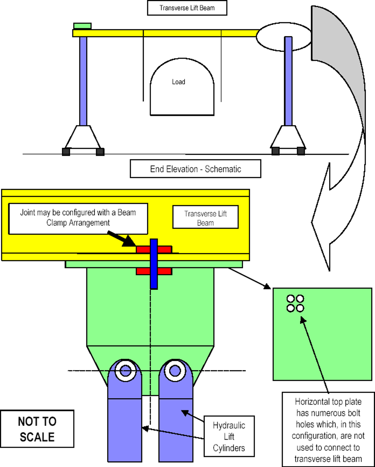
Figure 1 – Schematic
The system may be assembled as shown schematically above in figure 1. In this configuration, the horizontal top plate, which forms part of the connection to the vertical lift cylinders, is connected to the flange on the underside of the transverse lift beam via a ‘beam clamp’ arrangement.
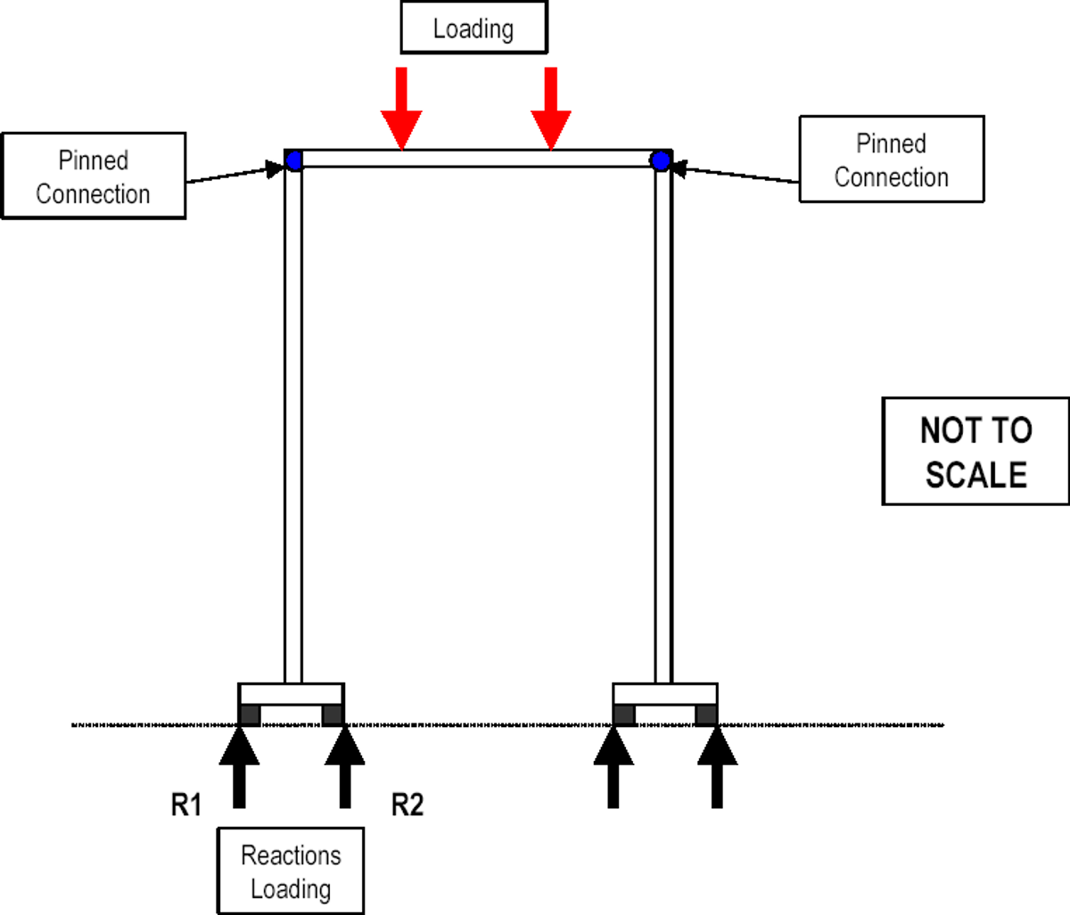
If it is configured in this way, the lifting arrangements may be represented by the structural idealisation shown in figure 2. In this case, the transverse stability of the system is derived from the moment generated by the difference in vertical reactions (at points R1 and R2) between the inner and outer guide rails. However, this may be limited as the supports may have no capacity to resist an uplift or tensile load.

Figure 2 – Structural idealisation
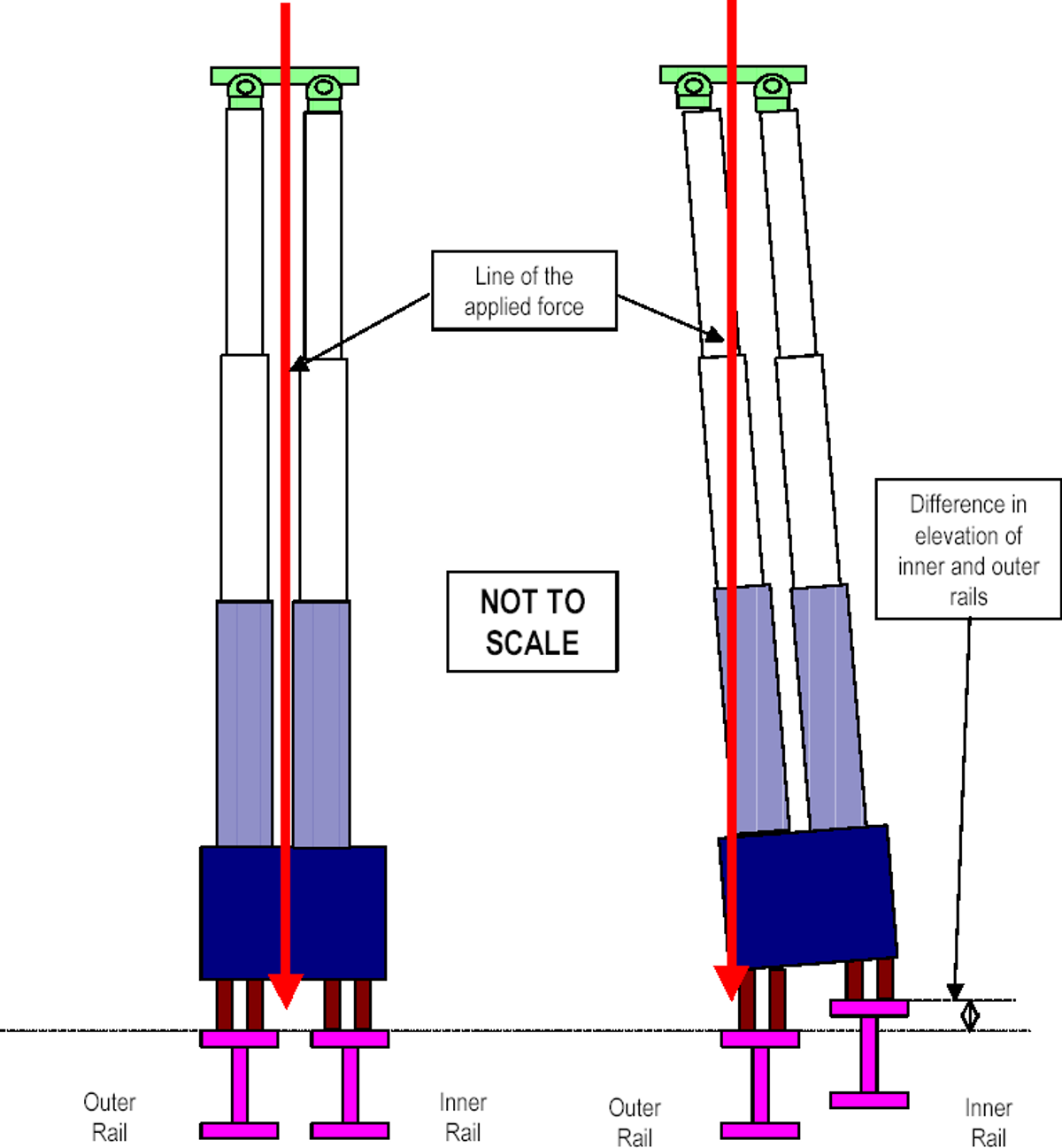
When the inner and outer guide rails are level, the line of action of the force is between the guide rails, as shown in figure 3A. If there are differential levels between the inner and outer guide rails, this may result in the line of action of the force moving outside the base, which in turn may impact the stability of the entire system, as shown in figure 3B.

Left (Figure 3A) – Inner and outer rails level; Right (Figure 3B) Difference in elevation between inner and outer rails
The company involved has made the following recommendations:
- A suitably qualified and competent person should check the stability of any lifting arrangements which incorporates similar vertical lift systems. This review should address the following issues:
- All possible conditions which may result in a differential deflection between the inner and outer guide rails at the base should be considered and their impact on the overall stability of the system fully evaluated.
- The permissible out-of-level tolerance between the inner and outer guide rails and the permissible tolerance for the vertical alignment of the lift units should be derived by calculation for all stages of the operation.
- All permissible tolerances should be included in the method statement and clearly communicated to all those involved in the operation.
- A system which is capable of monitoring the vertical alignment (in two orthogonal planes) of the hydraulic lift cylinders should be devised and used during the operation.
Related safety flashes
-
IMCA SF 02/03
1 February 2003
IMCA Safety Flashes summarise key safety matters and incidents, allowing lessons to be more easily learnt for the benefit of the entire offshore industry.
The effectiveness of the IMCA Safety Flash system depends on the industry sharing information and so avoiding repeat incidents. Incidents are classified according to IOGP's Life Saving Rules.
All information is anonymised or sanitised, as appropriate, and warnings for graphic content included where possible.
IMCA makes every effort to ensure both the accuracy and reliability of the information shared, but is not be liable for any guidance and/or recommendation and/or statement herein contained.
The information contained in this document does not fulfil or replace any individual's or Member's legal, regulatory or other duties or obligations in respect of their operations. Individuals and Members remain solely responsible for the safe, lawful and proper conduct of their operations.
Share your safety incidents with IMCA online. Sign-up to receive Safety Flashes straight to your email.