Two Walk-to-Work gangway incidents
- Safety Flash
- Published on 18 December 2025
- Generated on 7 April 2026
- IMCA SF 23/25
- 5 minute read
What happened?
A member reports two related incidents involving Walk-to-Work gangways.
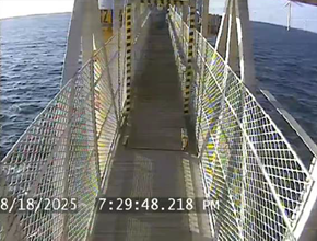
1) Uncontrolled movement of W2W Gangway / Collision with Crane
On 18 August, an SOV was engaged in W2W transfers on an Offshore Wind Farm. While initiating the connection with a Transition Piece (TP), the gangway slipped off the TP and slewed uncontrolled to the stern until it collided with the vessel crane. During the slew the operator tried to stop the movement by pressing the emergency stop button without effect. Following the collision the gangway went into auto-retraction mode. All W2W operations were stopped, and the gangway manufacturer was contacted for investigation and damage assessment. There were no injuries. Whilst the crane itself was undamaged, the gangway was damaged. This was considered a high potential incident.
 |
 |
What were the causes
Investigation identified the following immediate causes:
- Equipment failure: The telescopic part of the gangway froze after making contact with the TP. This malfunction caused the tele-tension mode (Bumper Mode) to become active, while the gangway was falsely registered as still being landed. In tele-tension mode the slewing movement of the gangway was in free drift. As a result, solely by gravity and vessel movement the gangway swung in an uncontrolled way astern, colliding with the crane.
- Inadequate barriers: The W2W gangway remained in Bumper Mode, during which the slewing movement of the boom was in free drift. When the gangway passes its operational limits, audible alarms warn the operator. However, as no automatic retraction or physical stop was activated in this case – there was no audible alarm.
- Differing instructions and manufacturer’s recommendations:
- The manufacturer’s manual suggests that the contact with the Transition Piece be made with a setpoint of “between 600 kg and a maximum of 1500 kg” [the setpoint represents the contact force required to maintain a secure connection with the structure while allowing the gangway to compensate for the vessels movement];
- A subsequent manufacturer’s recommendation (a “gangway safety bulletin” of 2017) stated that “the minimum setpoint shall be 800kg to ensure a safe connection”;
- The operators in this instance made the connection with a setpoint of approximately 700 kg.
The following root causes were identified
- Stiction – “static friction” in the hydraulic motor moving the telescopic part of the gangway caused the freezing. In the case where a motor is trying to rotate from a standstill (as it is when it is landed), and when the difference in pressure between the two sides of the motors is too small, it won't overcome that friction.
In order for the motor to operate, a certain pressure difference must be present between both sides of the engine. The manufacturer concluded that at the time of the incident this difference was too low to overcome the stiction of the engine. Therefore, leading to the freezing of the gangway while still being recognized as landed by the system.
Actions taken
- The hydraulic system was modified and then tested extensively alongside in port and then at sea; the identified root cause was reconfirmed and effectively mitigated.
- Other vessels and other operators with similar equipment were notified.
- Clear and unambiguous procedures for operation were developed and put in place.
- Engineered barriers and controls, both hardware and in software, were put in place to prevent this from happening again.
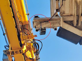
- Cameras were installed to enhance operational oversight and safety.
2) Telescopic W2W gangway not retracting properly
On 22 September the same vessel was doing the same kind of W2W transfer work. While preparing the connection to a Transition Piece (TP), the gangway operator followed the connection procedure. When activating “Bumper mode”, the operator noticed that the telescopic part of the gangway could not be retracted using the joystick. The issue was immediately reported to the bridge team and the connection aborted. The gangway moved back into parking position and the crew initiated investigation of the technical issue. No-one was harmed; there was no damage.
What was the cause?
- The immediate cause was found to be that the gangway could not retract due to insufficient pressure on the B Side of hydraulic motors. Pressure on the B side is required for the retraction of the telescopic part.
- The root cause was found to be that the hydraulic modifications installed to prevent stiction (see above incident of 18 August) had introduced a logic error in the automation system. The bypass valve for reducing the hydraulic pressure opens already when the operator is initiating the bumper mode, but before the actual physical contact with the TP is made and the bumper mode is activated. This very specific case was not identified during review and testing by the manufacturer.
What was the fix?
- Adjustment of the pressure reduction valve on the B-Side of hydraulic motor to a lower setting after analysis of the read-outs from the sensor logs. This valve is controlling the retraction of the telescopic part of the gangway when in bumper mode.
- Appropriate modification of the control automation logic and thorough testing by the manufacturer.
- Redesign of Valve Activation Logic and an update in software.
Related Safety Flashes
-
IMCA SF 15/25
19 August 2025
-
IMCA SF 07/19
18 April 2019
IMCA Safety Flashes summarise key safety matters and incidents, allowing lessons to be more easily learnt for the benefit of the entire offshore industry.
The effectiveness of the IMCA Safety Flash system depends on the industry sharing information and so avoiding repeat incidents. Incidents are classified according to IOGP's Life Saving Rules.
All information is anonymised or sanitised, as appropriate, and warnings for graphic content included where possible.
IMCA makes every effort to ensure both the accuracy and reliability of the information shared, but is not be liable for any guidance and/or recommendation and/or statement herein contained.
The information contained in this document does not fulfil or replace any individual's or Member's legal, regulatory or other duties or obligations in respect of their operations. Individuals and Members remain solely responsible for the safe, lawful and proper conduct of their operations.
Share your safety incidents with IMCA online. Sign-up to receive Safety Flashes straight to your email.